
There are, two circuit analysis rules that can be used to analyze any circuit, simple or complex. These rules are special cases of the laws of conservation of charge and conservation of energy. The rules are known as Kirchhoff’s rules, after their inventor Gustav Kirchhoff (1824–1887).
The following terms are important for the electric wheel:
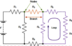
NODES: A node is the point of connection between two or more branches.
BRANCHES : A branch represents a single element such as a voltage source or a resistor. A branch represents a single element such as a voltage source or a resistor. A node is the point of connection between two or more branches.
LOOPS:– A collection of branches that form a closed path returning to the same node without going through any other nodes or branches twice.
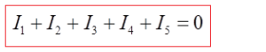
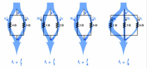
Example 1: Example: Knots, branches and loops in the electric wheel shown in the picture:
Kirchhoff’s rules for circuit analysis are applications of conservation laws to circuits. The first rule is the application of conservation of charge, while the second rule is the application of conservation of energy.
Kirchhoff’s First Rule
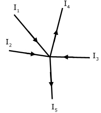
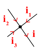
Kirchhoff’s first rule—the junction rule. The sum of all currents entering a junction must equal the sum of all currents leaving the junction.

Example:
The first rule is the application of conservation of charge.
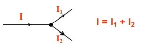
At any instant the algebraic sum of the currents flowing into any junction in a circuit is zero.
Example:
Kirchhoff’s Second Rule
Kirchhoff’s second rule requires. Rearranged, this is, which means the emf equals the sum of the IR (voltage) drops in the loop.
![]()
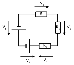
Kirchhoff’s Voltage Law: At any instant the algebraic sum of the voltages around any loop in a circuit is zero.
![]()
Applying Kirchhoff’s Rules
By applying Kirchhoff’s rules, we generate equations that allow us to find the unknowns in circuits. The unknowns may be currents, emfs, or resistances. Each time a rule is applied, an equation is produced. If there are as many independent equations as unknowns, then the problem can be solved. There are two decisions you must make when applying Kirchhoff’s rules. These decisions determine the signs of various quantities in the equations you obtain from applying the rules.
- When applying Kirchhoff’s first rule, the junction rule, you must label the current in each branch and decide in what direction it is going. For example, in Figure , currents are labeled I1, I2, I3, and I, and arrows indicate their directions. There is no risk here, for if you choose the wrong direction, the current will be of the correct magnitude but negative.
 2. When applying Kirchhoff’s second rule, the loop rule, you must identify a closed loop and decide in which direction to go around it, clockwise or counterclockwise. For example, in Figure 3 the loop was traversed in the same direction as the current (clockwise). Again, there is no risk; going around the circuit in the opposite direction reverses the sign of every term in the equation, which is like multiplying both sides of the equation by –1.
Figure in down and the following points will help you get the plus or minus signs right when applying the loop rule. Note that the resistors and emfs are traversed by going from a to b. In many circuits, it will be necessary to construct more than one loop. In traversing each loop, one needs to be consistent for the sign of the change in potential.
Example
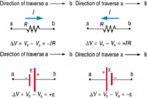
- When a resistor is traversed in the same direction as the current, the change in potential is –IR.
- When a resistor is traversed in the direction opposite to the current, the change in potential is +IR.
- When an emf is traversed from – to + (the same direction it moves positive charge), the change in potential is +emf.
- When an emf is traversed from + to – (opposite to the direction it moves positive charge), the change in potential is − emf.


")
