Simple circuits
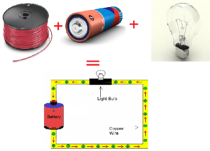
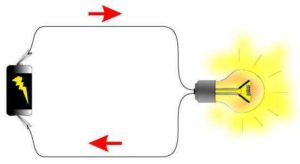
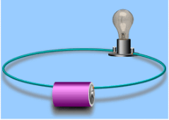
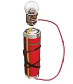
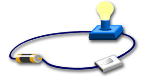
When charged particles build up in an object it is called static electricity. Another kind of electricity occurs when electrons flow in a current. A battery and wires can make current flow. Look at the simple electric circuit below. It consists of four parts: battery, a light bulb, a wire.
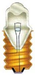
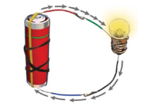
The battery pushes electrons from the negative terminal (where there are many electrons), through the switch, the light bulb, and the wire into the positive terminal (where there are not many electrons). As electrons pass through the wire and into the light bulb, a special kind of wire inside the bulb, called a filament, lights the bulb.
![]()
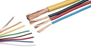
 The wire used in electric circuits is usually made of copper. Copper and silver are good conductors. Conductors carry electrons very easily.Rubber, plastic, and glass are good insulators. Insulators do not permit electrons to flow through them. Insulators are poor conductors of electricity and are therefore used to cover wires used in circuits.

Electricity needs a path to pass from the positive terminal to the negative terminal of an electric cell (battery). A connection that provides a path outside an electric cell, for the electricity to pass from the positive terminal to the negative terminal of the cell, is called an electrical circuit.
In a simple DC circuit, a resistive load as a bulb is connected between the positive and negative terminals of the battery.
For exam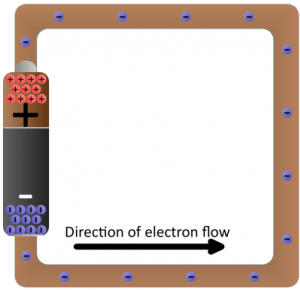 ple, a bulb glows only when the positive terminal and the negative terminal of an electric cell are connected to the two terminals of the bulb. If the wires from the bulb are connected to the same terminal (either positive or negative), then the bulb doesn’t glow.
An electrical circuit diagram is a simplified schematic representation of an electric circuit. It uses standard symbols for the components in the circuit and does not show the physical arrangements of the components
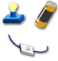
Conductors- wires ![]()
Source-battery 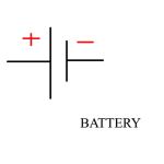
The light bulb

Circuit diagrams use symbols to represent the components in a circuit. We draw a circuit diagram like this:
What if you want to turn the light bulb off? You need to stop the flow of electrons. Look at the simple circuit. The circuit has been broken. The light bulb is not lit. The flow of electrons has stopped because there is a gap in the circuit, and the electrons no longer have a closed path.
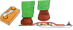
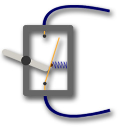
If you want to turn the light bulb back on, the switch must be closed to complete the circuit. When the spring pushes the metal strips together so they are touching, we say that the switch is ‘closed’. Electric current can then flow through the switch and around the circuit. When the switch is ‘open’ the metal strips are pushed apart so the current can’t flow. The best way of making a gap in your circuit to stop current flowing is to put in a switch.
 The switch is controlling the light bulb. If the switch is connected to the wire it will make the bulb light up. This is it is a closed circuit and has no holes in it to break the circuit. If it was not touching the wire it would be a open circuit because there’s a ‘hole’ in it.

The switcher symbol 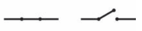
Open and closed circuits:
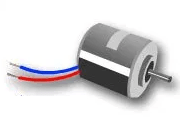
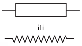
A load is any device that uses the energy of the flowing electricity. Typical loads are lights, motors, and appliances. When current flows through some load, electrical energy to be converted into some type of other useful energy. that does work. There are several types of loads, including resistance loads like incandescent light bulbs and heating elements, and inductive loads like motors.

We show them with a simple symbol:
Measuring amps and volts
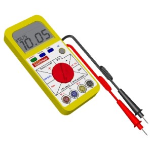
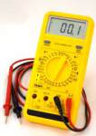
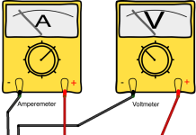 You need to know how to measure current and voltage. Current is measured in units called amps. A device called an ammeter is used to measure current. Voltage is measured in volts. Voltage is meaured using a voltmeter.
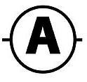

The symbol for amps is A. The symbol for volts is V.
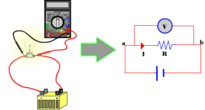
The ammeter is connected in series with the load and the voltmeter is connected in parallel with the load. Current is the measure of the rate of electron “flow” in a circuit. It is measured in the unit of the Ampere, simply called “Amp,” (A). The most common way to measure current in a circuit is to break the circuit open and insert an “ammeter” in series (in-line) with the circuit so that all electrons flowing through the circuit also have to go through the meter. Because measuring current in this manner requires the meter be made part of the circuit, it is a more difficult type of measurement to make than either voltage or resistance.
The voltmeter has a very high internal resistance and must be connected in parallel with the component you are measuring. You therefore need to connect it to two different points (which are usually, before and after a resistor). The voltmeter calculates the potential difference between those two points.
 Some types of voltmeter have a pointer on a dial, but most have a digital readout. You can measure the voltage across a cell or battery. The more cells, the bigger the voltage.
The diagram shows the correct connections for an ammeter and a voltmeter.
An ammeter for measuring a very low electrical current less than 1mA is called a galvanometer.
Series and Parallel Circuits
Normal Circuit
A basic circuit has 1 light bulb and 2 wires. Each wire will be connected to each side of the battery and the other sides of the wires will be connected to the light bulb

Series Circuit
In a series circuit there are 2 light bulbs (or more, never less otherwise it would be a normal circuit) and 4 wires. But in series circuit only to one light bulb will be directly connected to the battery, the other one will be connected to the first light bulb Here is a picture of a series circuit.

This is a series circuit. It is like a normal circuit but has multiple light bulbs. To make this simpler to understand pretend the switch is just a connected wire. In a series circuit there is only one route for electricity to run through. So if one bulb broke the other bulb will not light up even if it is not broken. This is because after the light bulb has been broken there is a ‘hole’ in the circuit. Now electricity can not run from the negative side to to the positive side.
![]()
Serial Circuit Diagram:
Parallel Circuit
 In a parallel circuit there are multiple routes for electricity to run from. There is lots of different ways to make a parallel circuit. But all parallel circuit has multiple ‘mini’-circuits in a big circuit This picture shows a parallel circuit that only has one light bulb that is directly connected to the battery the other light bulb is connected to the previous bulb.
In this parallel circuit there is two circuits that electricity can travel through. So if a bulb breaks in one of these circuits (2 circuit) the other bulb in the other circuit will continue to light up. This is because there are 2 ‘mini’-circuits in a big circuit. The electricity can choose either route to go through. That is why if one bulb broke only one ‘mini’-circuit is not complete. So the electricity can go through the other one.
Parallel Circuit Diagram:

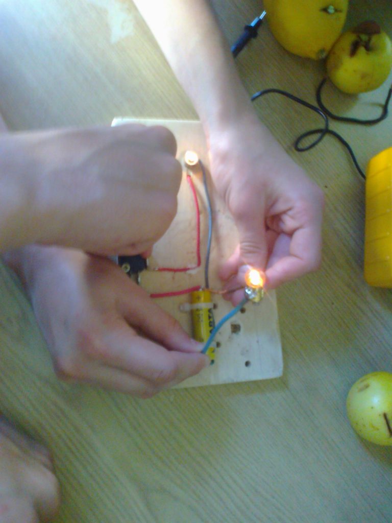
Make a simple circuits
 A simple circuit contains the minimum things needed to have a functioning electric circuit. A simple circuit requires three (3) things: A source of electrical potential difference or voltage. (typically a battery or electrical outlet) A conductive path which would allow for the movement of charges. (typically made of wire). An electrical resistance (resistor) which is loosely defined as any object that uses electricity to do work. (a light bulb, electric motor, heating element, speaker, etc.)
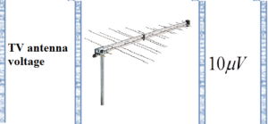
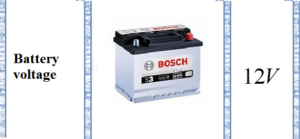
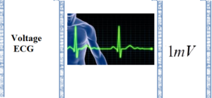
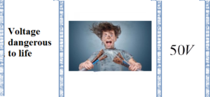
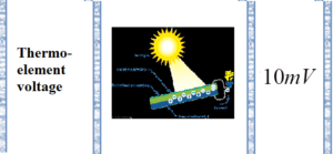
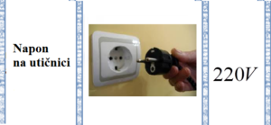
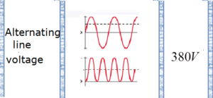
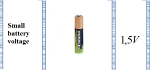
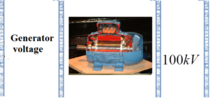
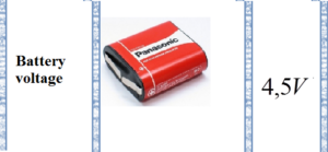
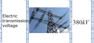
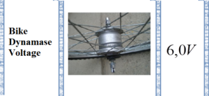
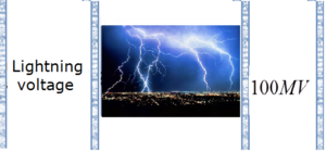
Some voltage values

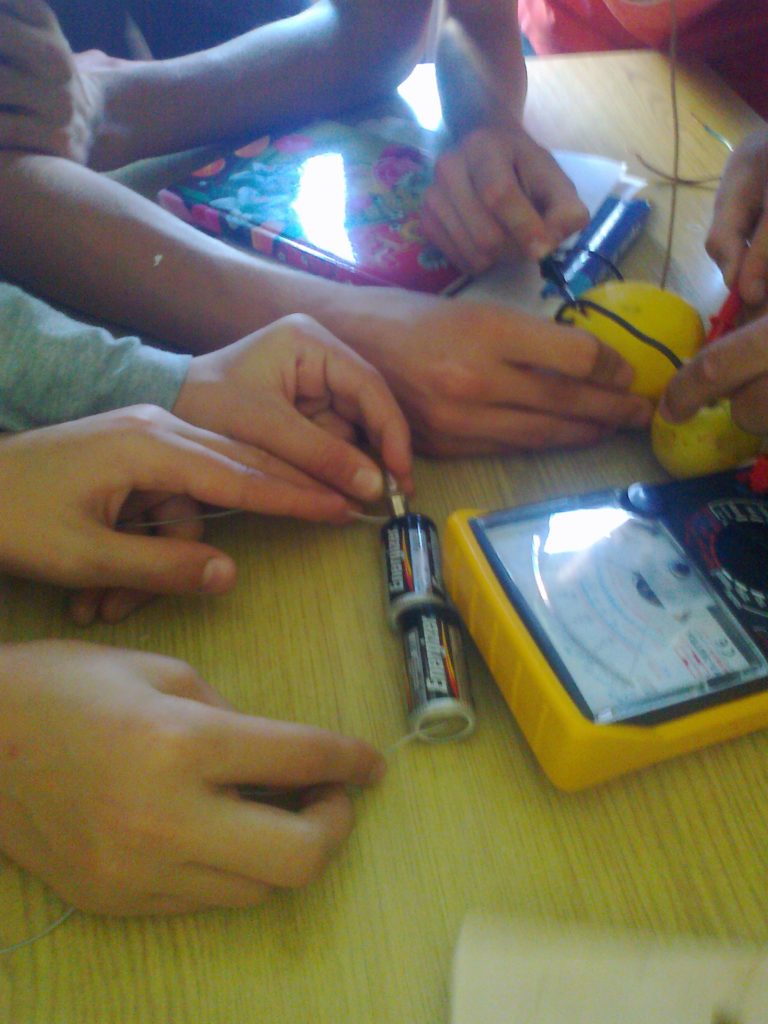
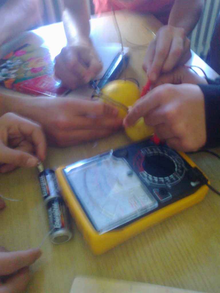
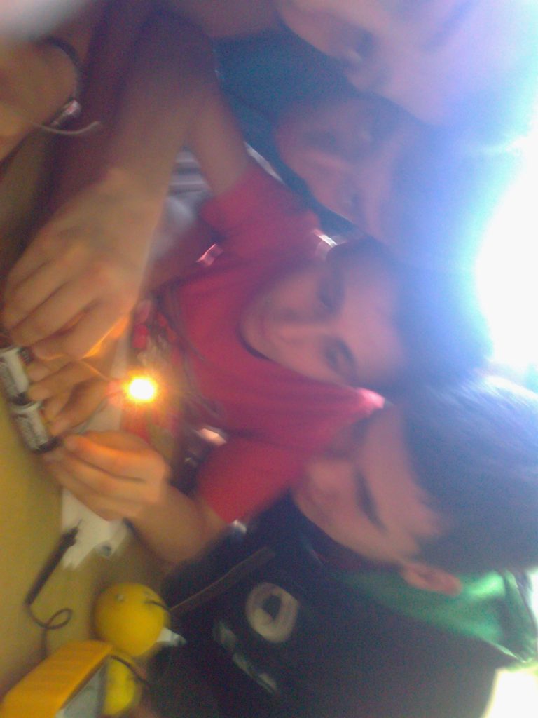
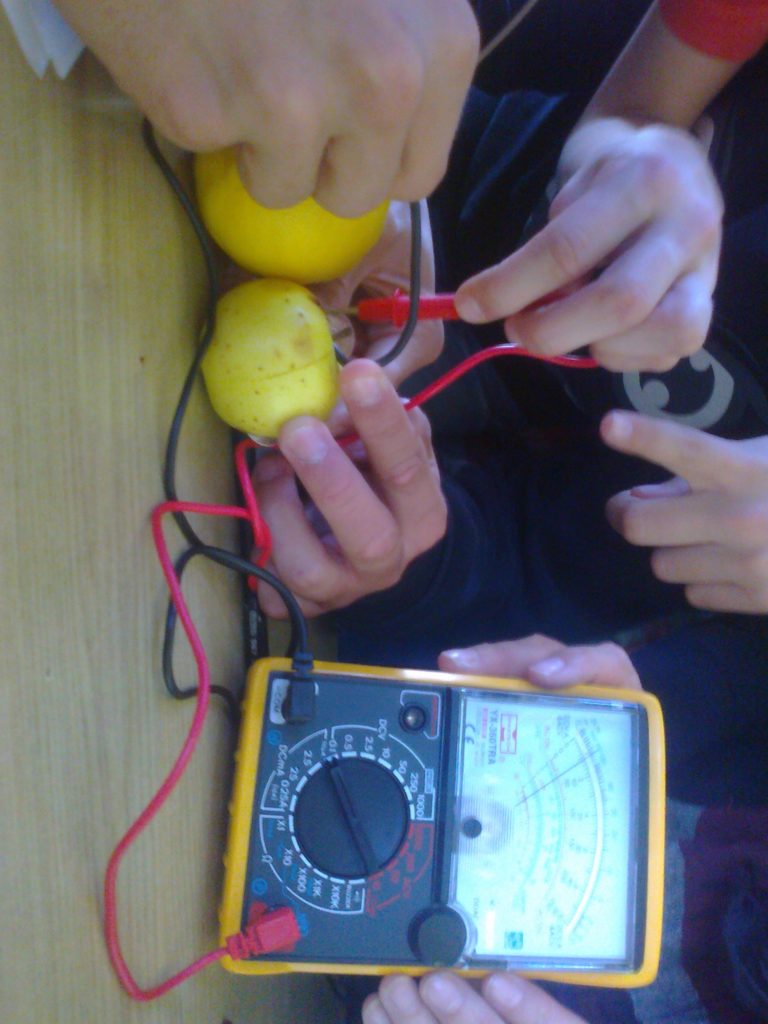
You can make a simple battery
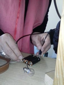
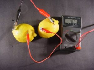 Using a battery is one of the most common ways of making electricity. A battery converts chemical energy into electrical energy. Car batteries are made up of a number of cells connected together and really the word cell should be used to describe a simple battery with only one cell. Many of the batteries that you use are really cells. You can make a simple battery by putting two rods, one of copper and one of zinc, into a lemon and connecting them to a torch bulb. The bulb should then light for a few seconds. The more lemons that you connect end to end the brighter the bulb. Connecting the lemons side by side will not change the brightness of the bulb but will make it last longer. If your lemon cell (battery) does not light a bulb try measuring the output voltage with a voltmeter.


")
