
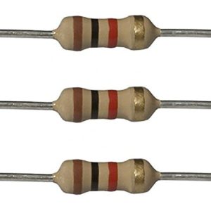
A resistor
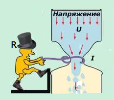
 The electricity moving through a wire or other conductor consists of its voltage (V), current (I) and resistance (R). Voltage is potential energy, current is the amount of electrons flowing through the wire, and resistance is the friction force on the electron flow.
What is a resistor?
Device that resists the flow of charges. Used to control current and voltage.
 Many kinds of resistors: Fixed and variable.
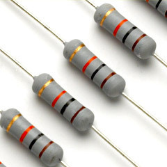
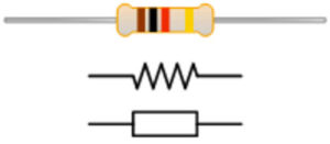
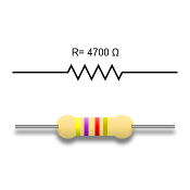
Fixed resistors have the same resistance for a wide range of temperatures, and electrical currents. Color code scheme allows us to figure out how much resistance it provides.
Resistors represents a given amount of resistance in a circuit. Resistance is a measure of how the flow of electric current is opposed or “resisted.”The value of fixed resistors cannot be changed.
 A potentiometer is a three-terminal resistor with a sliding or rotating contact that forms an adjustable voltage divider. If only two terminals are used, one end and the wiper, it acts as a variable resistor or rheostat.
A wide variety of potmeters exist. Manually adjustable potmeters can be divided in rotary or linear movement types. The tables below list the available types and their applications. Besides manually adjustable pots, also electronically controlled potentiometers exist, often called digital potmete
We can present resistors and other electrical devices with symbols.
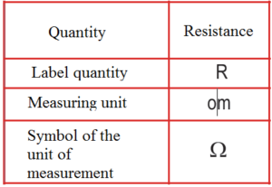
Resistance

 Resistivity is a fundamental material property while the material properties and the geometry of the component determine its resistance. An
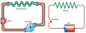
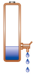
A conductor like a piece of metal has its atoms so arranged that electrons can readily pass around the atoms with little friction or resistance.This resistance is similar to the friction of the hose against the water moving through it.

Ohm is the unit of measurement of the electrical resistance. In a nonconductor or poor conductor, the atoms are so arranged as to greatly resist or impede the travel of the electrons.
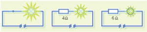
Example: In the figure below, the bulb is illuminated brightly if the resistor is not connected to the wheel. Bulb lowlights when a 4Ω resistor is connected and even weaker when a 6Ω resistor is connected.
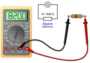
The instrument for measuring the optic is called the ommeter.
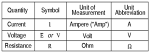
What is the relationship between current, voltage and resistance?
Ohm’s Law explains the relationship between voltage (V or E), current (I) and resistance (R)
There are two way to prove that:
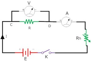
Method 1: We use a circuit where we change the battery value and note the value current of each battery value.
Method 2: We use a fixed voltage battery using variable resistance and changing of resistance we take current and voltage rating each time.
Apparatus required:
- Battery
- Voltmeter
- Ammeter
- Resistor
- Variable resistor
- Switch
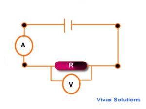
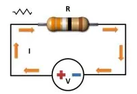
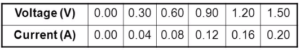
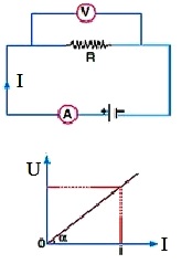
Example: These are used to show how the current through a component varies with the applied voltage.The circuit opposite could be used to obtain a current-voltage graph of a resistor.The variable resistor is used to apply a range of voltages across the resistor.Typical results:
The current-voltage graph of a wire or a fixed resistor at a constant temperature
The graph is a straight line through the origin.The wire or resistor obeys Ohm’s law which states that that the current is proportional to the voltage.
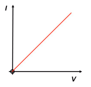 An electric current will only flow around a circuit if there are no gaps in the circuit.All components have resistance. The greater the resistance the smaller is the current for the same applied voltage. Resistance is measured in ohms. A current – voltage graph for a resistor is a straight line through the origin. This shows that the current through the resistor is proportional to the applied voltage.current
I vs. U graph = straight line, R is same, for all values of I and U, R = slope of the line
![]()
![]()
Example2: Repeat the experiment five times by changing current in the circuit with the help of rheostat. Note the readings in the table.
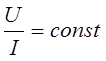
From the above table it is observed that the ratio ![]() is always constant. Hence ohm’s law is verified. i.e. The resistance of a conductor remains constant at constant temperature no matter what applied voltage is used to measure it.
is always constant. Hence ohm’s law is verified. i.e. The resistance of a conductor remains constant at constant temperature no matter what applied voltage is used to measure it.
Ohm’s Law
Ohm’s Law
Ohm’s Law
Georg Ohm • Georg Simon Ohm (16 March 1789 – 6 July 1854) was a German physicist and mathematician. As a school teacher, Ohm began his research with the new electrochemical cell, invented by Italian scientist Alessandro Volta. Using equipment of his own creation, Ohm found that there is a direct proportionality between the potential difference (voltage) applied across a conductor and the resultant electric current. This relationship is known as Ohm’s law.
Om’s law for a part of the circuitry
Ohms Law Relationship
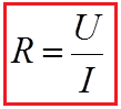
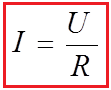
Ohm’s law states that the electrical current through a conductor is proportional to the potential difference across it. Furthermore, the electrical resistance of the conductor is constant. This leads to the mathematical equation:
where I is the current in amperes, U the voltage in volts and R the resistance in ohms. To illustrate: a resistor of one ohm subjected to a current of 1A has a voltage difference of 1V across its terminals. The equation is named after Georg Ohm.
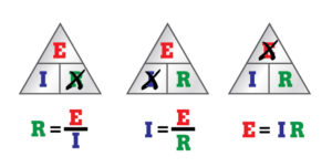
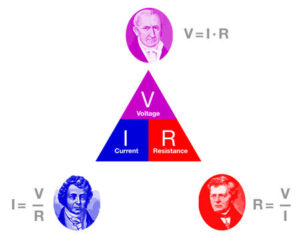
Ohm’s Law expresses the relationshipbetween the current (I), the voltage (E),and the resistance (R) in a circuit.Ohm’s Law can be expressed in threedifferent ways, and can be applied tothe entire circuit or to any part of acircuit. When any two factors areknown, the third unknown factor can becalculated from Ohm’s Law.

Where is:![]()
By knowing any two values of the Voltage, Current or Resistance quantities we can use Ohms Law to find the third missing value. Ohms Law is used extensively in electronics formulas and calculations so it is “very important to understand and accurately remember these formulas”.
Ohms Law Triangle

It is sometimes easier to remember this Ohms law relationship by using pictures. Here the three quantities of U, I and R have been superimposed into a triangle (affectionately called the Ohms Law Triangle) giving voltage at the top with current and resistance below. This arrangement represents the actual position of each quantity within the Ohms law formulas.
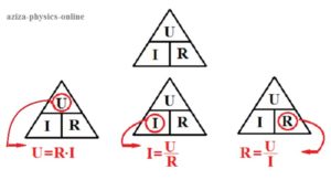
Transposing the standard Ohms Law equation above will give us the following combinations of the same equation:
Then by using Ohms Law we can see that a voltage of 1V applied to a resistor of 1Ω will cause a current of 1A to flow and the greater the resistance value, the less current that will flow for a given applied voltage. ![]() .
.
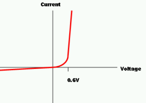
Any Electrical device or component that obeys “Ohms Law” that is, the current flowing through it is proportional to the voltage across it ( I α V ), such as resistors or cables, are said to be “Ohmic” in nature, and devices that do not, such as transistors or diodes, are said to be “Non-ohmic” devices.
Om’s law applies only to metallic conductors. Om’s law does not apply to the human body and diode.

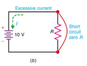
Short circuits
A short circuit happens when electric current can flow round a circuit from one terminal of the battery to the other without passing through any components. In a short circuit, the wire heats up and battery will go flat.
Om’s law for a entire circuit
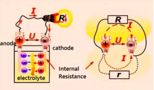
EMF and Potential Difference
In any circuit there are components that put energy in to the circuit and components that take energy out. From now on, we will say that any device putting energy into a circuit is providing an electo-motive force (emf) and any device taking it out has a potential difference DV across it.
Internal Resistance
Cells and batteries are not perfect (what is – apart from the moment your last exam finishes, of course?). Use them for a while and you will notice they get hot.
Where is the heat energy coming from?
It’s from the current moving through the inside of the cell. The resistance inside the cell turns some of the electrical energy it produced to heat energy as the electrons move through it.
You need to consider the internal resistance when deciding if a cell is appropriate to use in a particular circuit. For the greatest efficiency the external resistance must be much greater than the internal resistance of the cell.
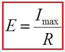
Power supplies which deliver low voltages and higher currents, like a car battery, need to have a low internal resistance, as shown above. High-voltage power supplies that produce thousands of volts must have an extremely high internal resistance to limit the current that would flow if there was an accidental short-circuit.
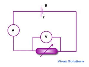
Finding Internal Resistance Experimentally
As U = E – Ir, if you plot a graph of terminal pd, V, against current, I, the gradient of the graph will be equal to the internal resistance of the cell. (negative because the graph slopes down)
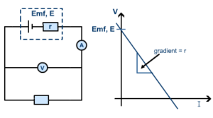
By recording values of current and terminal pd as the external resistance changes you can plot the graph and find the internal resistance and the emf of the cell. If there is more than one cell in series the internal resistances of the cells must be added. This equation can be written as follows:
![]()
where RI is the voltage drop of a part of the circuit. The voltage can be calculated using the expression:
![]()
The electric motor (voltage at the source) is smaller than the voltage drop on the internal resistance sources. When the switch is open, there is no drop in voltage on the internal resistance then U = E
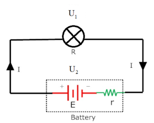
The circuit which carries same current on every branch called simple circuit. A simple circuit is shown in figure.
Where is:
E = Electromotive force
r = internal resistance of the battery
I = total current of the circuit
R = resistance of bulb
U1 = voltage of bulb
U2 = voltage of battery
Applying Ohm’s law in the simple circuit
We know Ohm’s law, ![]()
Battery voltage, ![]()
It is called lost voltage of battery. Because internal resistance of battery drops it.
Bulb voltage ![]()
Battery and the bulb are carrying same current I.
![]()
![]()
![]()
Total current flow = electromotive force of battery / Total resistance of circuit
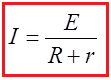
It can be said that current of a circuit is proportional its electromotive force of the circuit and inversely proportional to the resistance of the circuit. Increase of electromotive force increases current, decrease of resistance increases current flow and increase of resistance decreases current.


")
